A Solver-efficient Computational Fluid Dynamic Approach for the Thermal Performance Analysis of Ventilated Façades
Department of Architecture, Built environment and Construction engineering, Politecnico di Milano, Italy
Email: sofia.pastori@polimi.it; giacomo.scrinzi@polimi.it; enrico.mazzucchelli@polimi.it; angelo.lucchini@polimi.it
*Corresponding author
Abstract. The paper deals with the use of Computational Fluid Dynamics (CFD) for the thermal performance analysis and optimisation of prefabricated Timber-Concrete Composite (TCC) ventilated façades. TCC envelopes are composed of an internal insulated timber-frame wall coupled to an external concrete slab, separated by a ventilated air cavity. Such systems join the properties of engineered timber (good seismic behaviour, low thermal conductivity, environmental sustainability, and ease of system integration) with those of concrete (high thermal inertia, excellent durability and fire resistance). There is very limited knowledge on the performance of TCC facades, especially for what concerns their thermal behaviour. For this reason, a TCC ventilated façade located in the north of Italy was monitored over one year, and the results collected were used to calibrate and validate a CFD model. A new solver algorithm was developed to speed up the CFD simulations, allowing up to 45 times faster analysis compared to conventional solvers. Thanks to this improvement, the final model is suitable to be used for time-efficient thermal analysis (a full-day real-time simulation takes approximately 23 minutes), limiting the expensive and time-consuming construction of mock-ups. The CFD model developed is suitable for the thermal performance analysis and optimisation of TCC ventilated facades, but also for generic ventilated facades with external massive cladding, both in the case of new and existing buildings.
Keywords: Ventilated façade, CFD, Energy efficiency, Timber-concrete composite façade, Building monitoring.
1. Introduction
In recent years, the construction industry has witnessed significant growth in the adoption of engineered timber products, both for new and existing buildings. This is primarily due to their good characteristics, such as excellent seismic performance, good thermal insulation, environmental sustainability and good behaviour under fire. Additionally, timber is highly compatible with prefabrication processes and systems integration, and can be easily disassembled at the end of its lifecycle [1]. On the other side, its limitations are mainly related to its fragile stress-strain behaviour, hygroscopic properties and low durability if not adequately protected [2].
In the realm of building envelopes, lightweight timber facades typically exhibit lower thermal inertia and acoustic insulation than higher-mass alternatives. On the other hand, massive timber solutions involve considerable use of virgin materials and high costs. To address these limitations and enhance performance in terms of structural behaviour, acoustic properties, fire resistance, and durability, timber structures are often combined with concrete, resulting in timber-concrete composite (TCC) systems [3].
TCC facades generally consist of an internal insulated timber wall coupled with an external concrete slab, which acts as a protective barrier against adverse weather conditions [4], particularly extreme events like hailstorms and windstorms. These hybrid facades merge the advantages of timber – i.e., light weight, excellent thermal insulation, sustainability, ease of prefabrication and systems integration, aesthetic appeal – with the benefits of concrete – i.e., mechanical strength, high thermal inertia, good acoustic insulation, durability, fire resistance, application of heavy claddings (e.g., tiles or stone) – [5].
Beyond timber-based construction, another widely studied topic is the use of ventilated facades and their advantages in terms of thermal, acoustic, and water-tightness properties [6].
TCC technology can be applied to ventilated facades. In this case, the presence of an air cavity between the timber wall and the concrete slab is needed to separate the external (potentially humid) concrete slab and the internal insulated timber wall, which must always be dry to prevent material degradation.
A comprehensive evaluation of the thermal performance of ventilated facades remains a key focus in current research. These systems interact in complex ways with the external environment, necessitating experimental investigations and CFD analyses to model the airflow within the cavity [7]. Over the past two decades, numerous studies explored the thermal behaviour of ventilated facades through experimental and numerical approaches [7-8]. Typically, these studies involve experimental monitoring, followed by analytical or CFD-based assessments. However, only a limited number of these CFD studies validate their findings against experimental data. Experimental monitoring, barring unexpected sensor errors, tends to yield reliable results, but these are closely tied to specific case studies [9]. On one hand, analytical methods have a long-established history and are known for their reliability, as evidenced by numerous studies. These methods involve simplified processes grounded in physical correlations, whose validity has been repeatedly confirmed over time [10]. On the other hand, CFD simulations provide a higher degree of detail, but are relatively new and less extensively validated, leading to greater uncertainties and the need for experimental validation [4]. One of the primary challenges in applying CFD techniques within the building physics domain is the significant computational power required [11]. This limitation has historically confined CFD studies to steady-state analyses or very short dynamic periods [12-14]. Despite these challenges, CFD’s ability to deliver highly precise information about flow fields makes it a valuable tool for evaluating the impact of design details in ventilated facades. For instance, research has examined airflow around venetian blinds [15], facade openings [16], and various shading systems [17].
The integration of experimental analysis and CFD modelling is widely regarded as the most comprehensive and accurate approach to evaluating the thermal behaviour of ventilated facades [9]. This combination was considered for the current investigation of ventilated facades with external massive cladding. Specifically, a TCC envelope was examined, a topic with limited prior research [4, 18], and for which no rigorous CFD modelling studies have been identified.
The objective of the research was to develop a solver-efficient CFD model for analysing the thermal performance of ventilated façades. Specifically, the first sub-goal was to implement the model and a novel solver algorithm to speed up the simulation process compared to conventional solvers. The second sub-goal was the model calibration and validation against experimental results, which were previously collected during the façade monitoring over one entire year [19].
The innovative aspect of the research is the implementation of a fast and accurate CFD model for the thermal performance prediction and optimization of ventilated facades with massive cladding, which can be used for new or refurbished buildings.
2. Methods
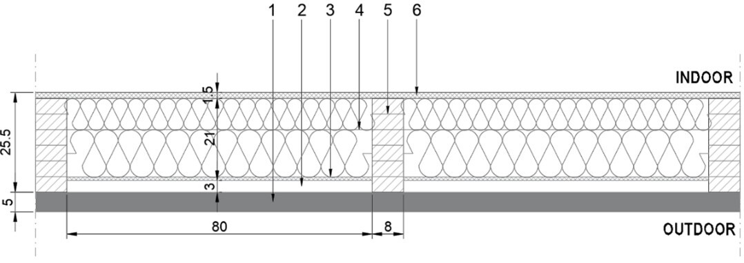
For the development of the CFD model, the prefabricated TCC ventilated façade system in Figure 1. was considered. It is composed of an internal timber frame structure coupled with an external 50 mm thick reinforced concrete slab, separated by independent vertical ventilated air cavities. The concrete slab has sealed joints, which means that each air cavity is connected to the external environment only at the bottom and top of the façade. The height of the air cavity depends on the building elevation and the presence of windows and/or protruding slabs.
The thermal behaviour of the TCC façade was preliminary monitored experimentally, to collect all the data needed for calibrating the numerical model. For this purpose, a 3-storey building with a TCC ventilated envelope was built and monitored for over a year in the north of Italy. In this case, the ventilated façade’s height is equal to two storeys of the building (the ground floor has a different envelope system), which is the minimum height that allows gaining some benefits from the natural ventilation inside the cavity of the façade, according to the literature. The monitoring started in August 2022 and ended in August 2023 [19]. The collected data were then used to set, calibrate and validate the CFD model, which was developed using the open-source software OpenFOAM [20]. All simulations were run on a computer with Dual XEON 6x CPUs and 48 GB of RAM.
2.1 Geometry of the model
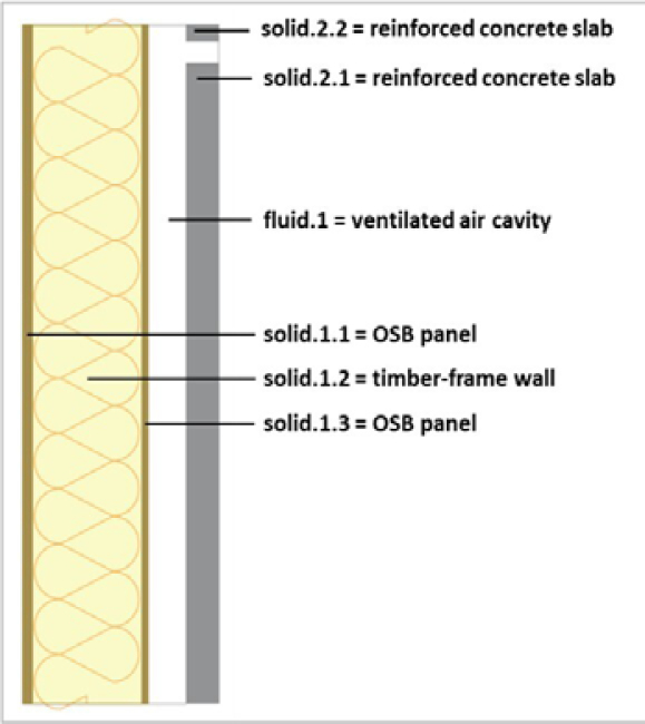
A two-dimensional analysis was performed to keep the model as simple as possible. This choice was compatible with the envelope configuration, since the air flows through many vertical independent façade cavities characterized by limited width (800 mm), hence horizontal air flow is negligible. For this reason, a 2D model that neglects the third spatial dimension was considered adequate for the study purpose. The model geometry developed is shown in Figure 2.
2.2 Physical properties of the model
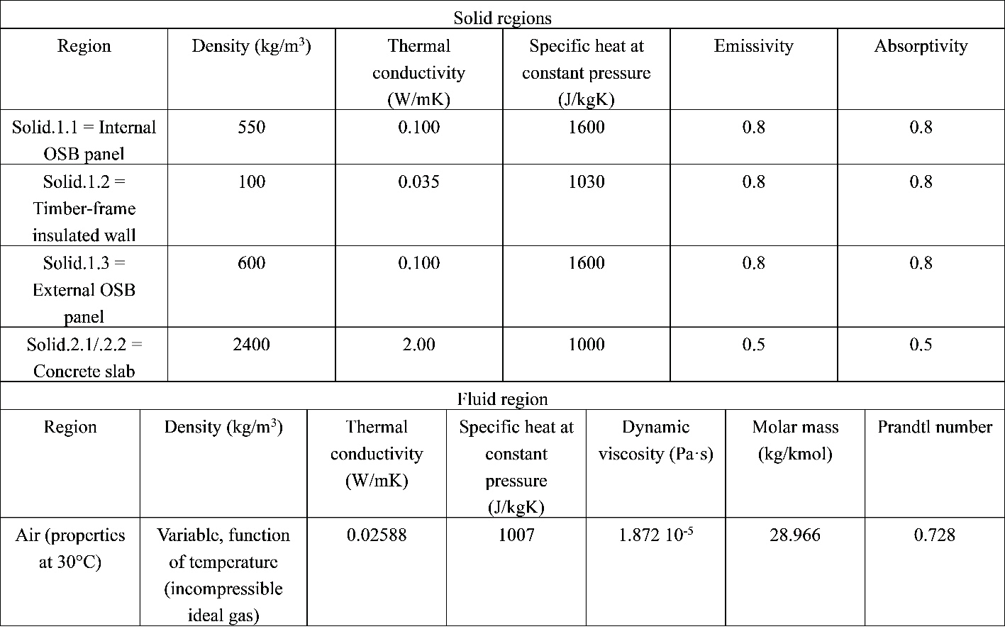
The thermo-physical properties assigned to each material (i.e. each region) in the CFD model are reported in Table 1. The materials’ characteristics were taken from the technical datasheets of the products used for the envelope.
2.3 Boundary conditions
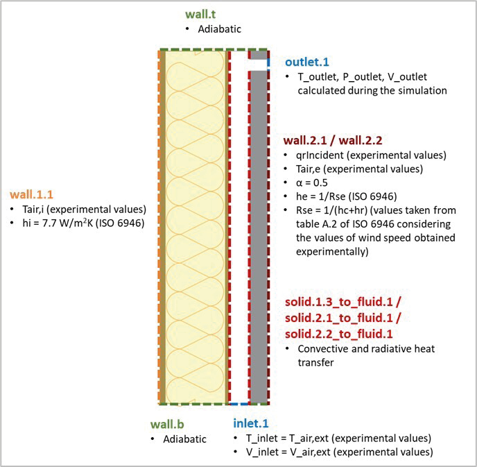
The boundary conditions applied to the model are shown in Figure 3. The trends of the variables T_air,i (indoor air temperature), T_air,e (outdoor air temperature), qr_incident (incident solar irradiation on the façade), and V_air,e (air velocity at the bottom inlet of the cavity) were taken from the experimental monitoring. The values of hi (convective-radiative coefficient of indoor environment), he (convective-radiative coefficient of outdoor environment), Rse (surface resistance of outdoor environment) were taken from the Standard ISO 6946 [21]; the values of T_outlet (air temperature at the top outlet of the cavity), P_outlet (air pressure at the top outlet of the cavity), V_outlet (air velocity at the top outlet of the cavity) are calculated by the software during the simulation.
2.4 Mesh
A mesh refinement study was developed to identify the best model discretization in terms of accuracy of the results and computational cost/time. Three meshes were tested by setting a simple simulation case, and the accuracy of the results obtained from the simulations was compared.
The meshes tested were:
– m0001_baseMesh
– m0002_baseMeshx1.5
– m0003_baseMeshx1.5x1.5
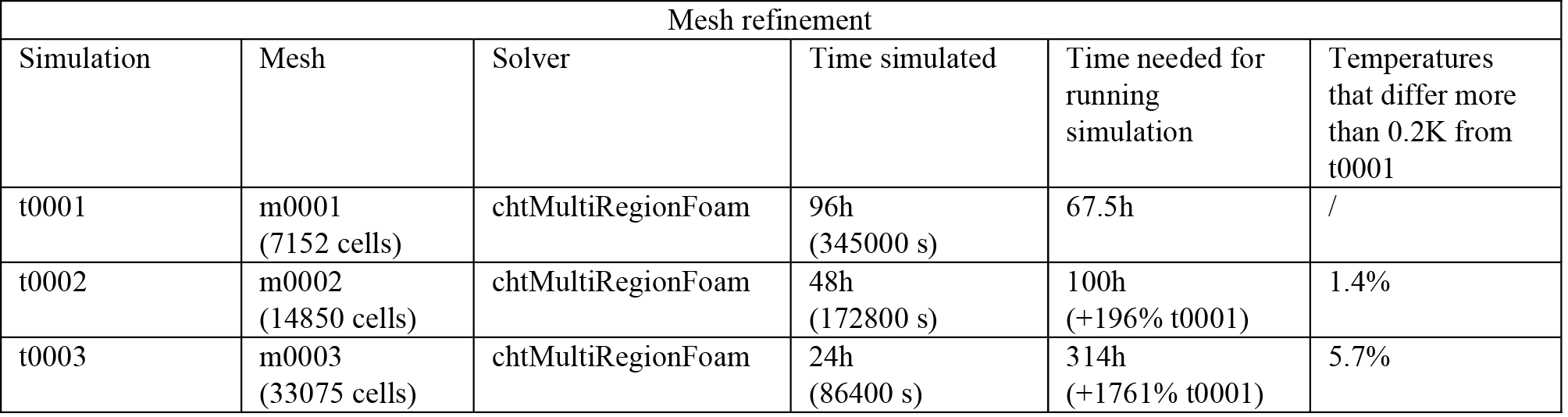
The number of cells for each mesh is equal to the number of the previous one multiplied by 1.5 in both vertical and horizontal directions. As expected, the results obtained show that the grid refinement produces slightly better accuracy, but with higher computational time. In this specific case, the mesh refinement does not produce consistent differences in the results, while the time needed for the computation increases considerably (see Table 2). For this reason, the coarser mesh (m0001) was chosen and used for all the simulations (Figure 4).
The first simulation (t0001) was run for 96 hours (4 days) to evaluate the amount of time needed by the model to catch the correct temperature trends. According to the results, 48 hours were enough for that, thus the second case (t0002) was run for 48 hours. The third simulation (t0003) was stopped just after 24 hours due to the huge computational time required to end the analysis.
2.5 The new “frozen-unfrozen flow” solver
At first, the conventional solver “chtMultiRegionFoam” was used. This solver allows for coupling a transient fluid flow with heat transfer between regions, buoyancy effects, turbulence, and radiation. It follows a segregated solution strategy, which means that the equations for each variable characterizing the system are solved sequentially and the solution of the preceding equations is inserted into the subsequent equation. The coupling between fluid and solid regions follows the same strategy: first, the equations for the fluid are solved using the temperature of the solid of the preceding iteration to define the boundary conditions for the temperature in the fluid. After that, the equation for the solid is solved using the temperature of the fluid of the preceding iteration to define the boundary condition for the solid temperature. This iterative procedure is executed until convergence is achieved. For each fluid region, the compressible Navier-Stokes equations are solved; for the solid regions, only the energy equation has to be solved. The regions are coupled by a thermal boundary condition.
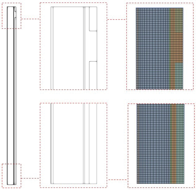
Starting from that, a novel solver algorithm called the “frozen-unfrozen flow” was developed to speed up the simulations, by switching the solution mode to “frozen” (i.e. no update of the velocity and pressure fields, allowing large time steps) and “unfrozen” (i.e. solution of all transport equations, with normal time steps) sequentially. The normal time step in the “unfrozen” mode is determined by the Courant number and the solid diffusion numbers, while the time stepping in the “frozen” mode is set based on user input. Figure 5. shows the schematic view of this algorithm: it starts with the initial time ( and several cycles with unfrozen (red zones) and frozen (blue zones) mode are repeated till the end of the simulation. For stability reasons, a transition mode (grey zones) is considered when the flow mode is switched between “frozen” and “unfrozen”.
2.6 Testing of the new solver
New cases were created to test the new solver performance, varying the length of frozen and unfrozen periods of time, respectively τfrozen and τunfrozen, in a systematic way to explore the effect of these numerical parameters on the accuracy of the results (i.e. the temperature values obtained in the model) and the time needed for the computation. The new cases were compared to a baseline case, t0001, identical to the new ones but run with the old solver. Table 3 resumes the results obtained from the new cases. All the simulations were run for 24 hours real time.
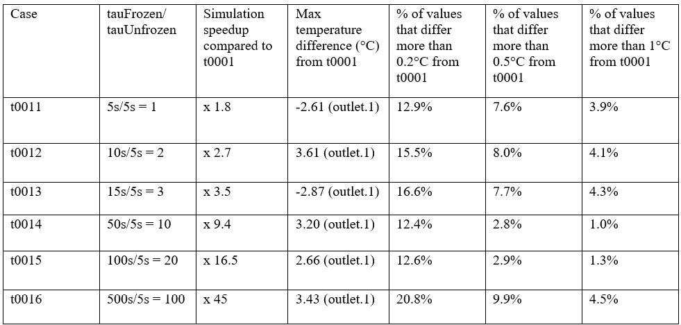
As expected, the simulation speed increased by increasing the ratio τfrozen /τunfrozen, while the accuracy did not appear to be inversely proportional to the speed.
2.7 CFD model calibration
The calibration process was developed by comparing the results obtained from the CFD model with the experimental data collected. It consisted of changing the physical and numerical parameters used in the modelling until the CFD results were aligned with the experimental ones.
For this process, the experimental data collected during summer days with clear sky (from the 23rd to the 27th of August 2022) for the south-oriented building façade were considered. The solver chtMultiRegionFoam was used for the calibration process, since the “frozen-unfrozen flow” solver was still under development.
2.8 CFD model validation
After calibrating the CFD model against experimental results obtained during summer days with a clear sky, the model was tested again considering different weather conditions. This process serves as model validation and is necessary to see whether the developed model also works under different boundary conditions. In this case, the experimental data collected during summer days with an overcast sky (registered from the 17th to the 21st of August 2022) were considered. The façade considered was again the south elevation of the building. For the present research objective, the validation process to test the model accuracy was performed considering only one new case. A more in-depth study should involve a greater number of cases for model validation, testing the calibrated model by changing several parameters (e.g. cavity depth, different weather conditions, etc.).
3. Results
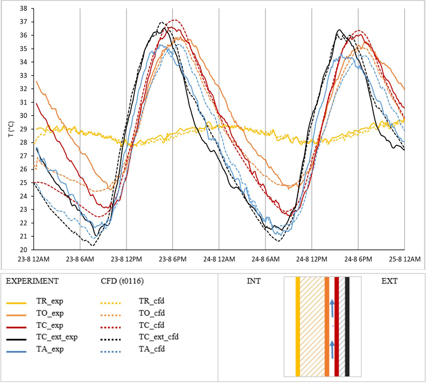
In this chapter, the results obtained by running the CFD model developed are presented and discussed. Figure 6. shows the graphical comparison between the temperatures measured experimentally and those predicted by the calibrated CFD model. The calibrated model (t0116) was able to predict the façade thermal behaviour with a very limited error compared to the experimental values obtained. The error was calculated for each surface of the wall as the difference between the mean temperature measured experimentally on that surface and the one calculated on the same surface by using the CFD model. For the error calculation, only the last 24 hours of each simulation were considered to exclude inaccurate values due to the initialization process at the beginning of each CFD case. The error obtained between experiment and CFD is: 0.19°C for TR, 1.3°C for TO, 0.8°C for TC and 0.9°C for TC_ext. Thus, the mean error between the values measured experimentally and those obtained from the CFD model is 0.8°C.
3.1 Validated model
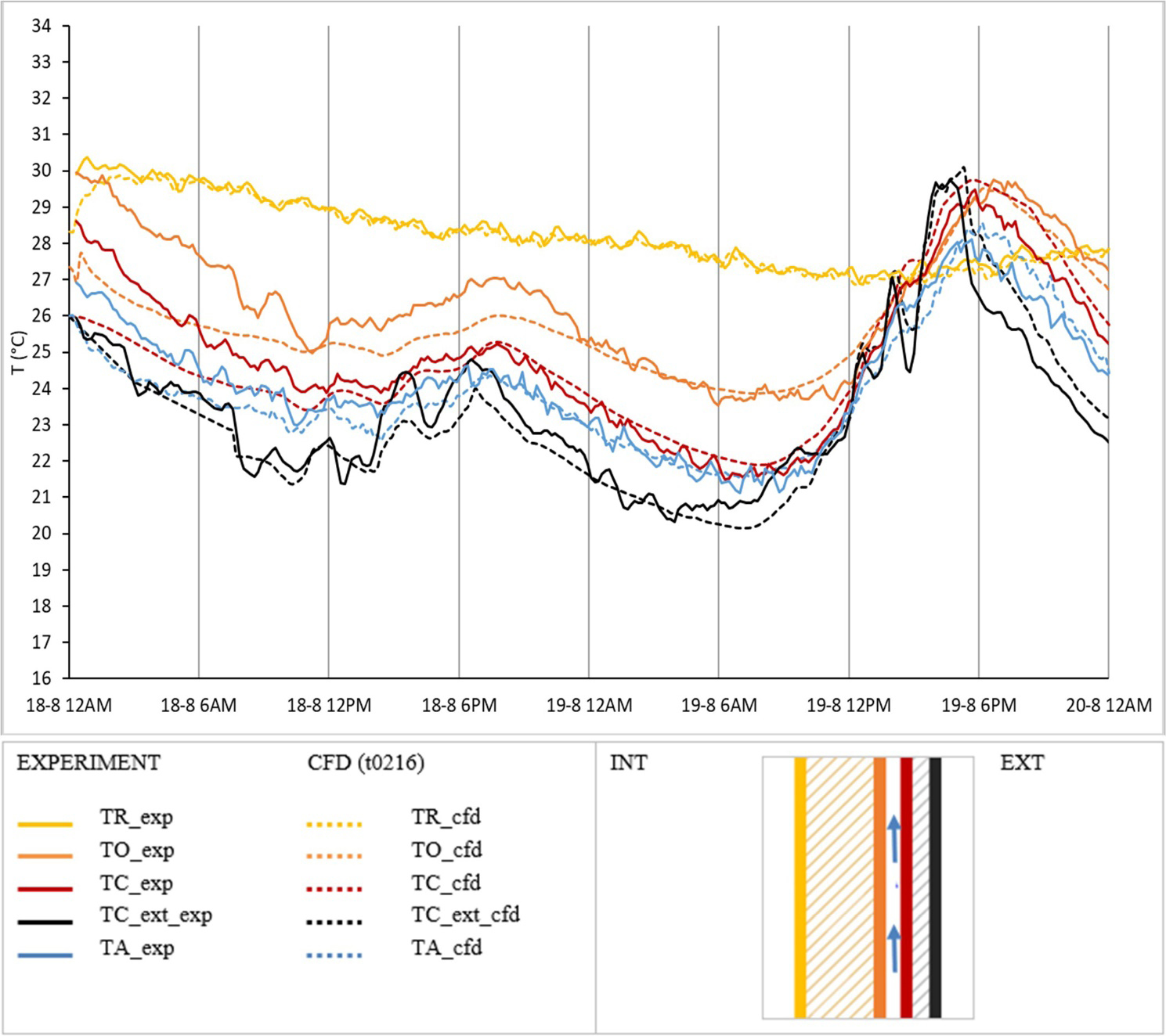
The calibrated model (t0116) was then tested considering different boundary conditions, in order to evaluate the accuracy of the prediction, also for a different case. For this reason, a new case (t0216) was set up by changing the weather conditions to summer days with an overcast sky. Figure 7 shows the comparison between the CFD results and the experimental data. In this case, the error obtained between experiment and CFD is: 0.22°C for TR, 0.8°C for TO, 0.6°C for TC and 0.6°C for TC_ext. Thus, the mean error between the values measured experimentally and those obtained from the CFD model is 0.6°C, slightly lower than the previous case.
3.2 Prediction of the thermal behaviour
After the CFD model validation, some of the input parameters might be changed (e.g. façade geometry, materials, weather conditions, etc.) to understand their influence on the façade’s thermal behaviour and study an optimised envelope configuration.
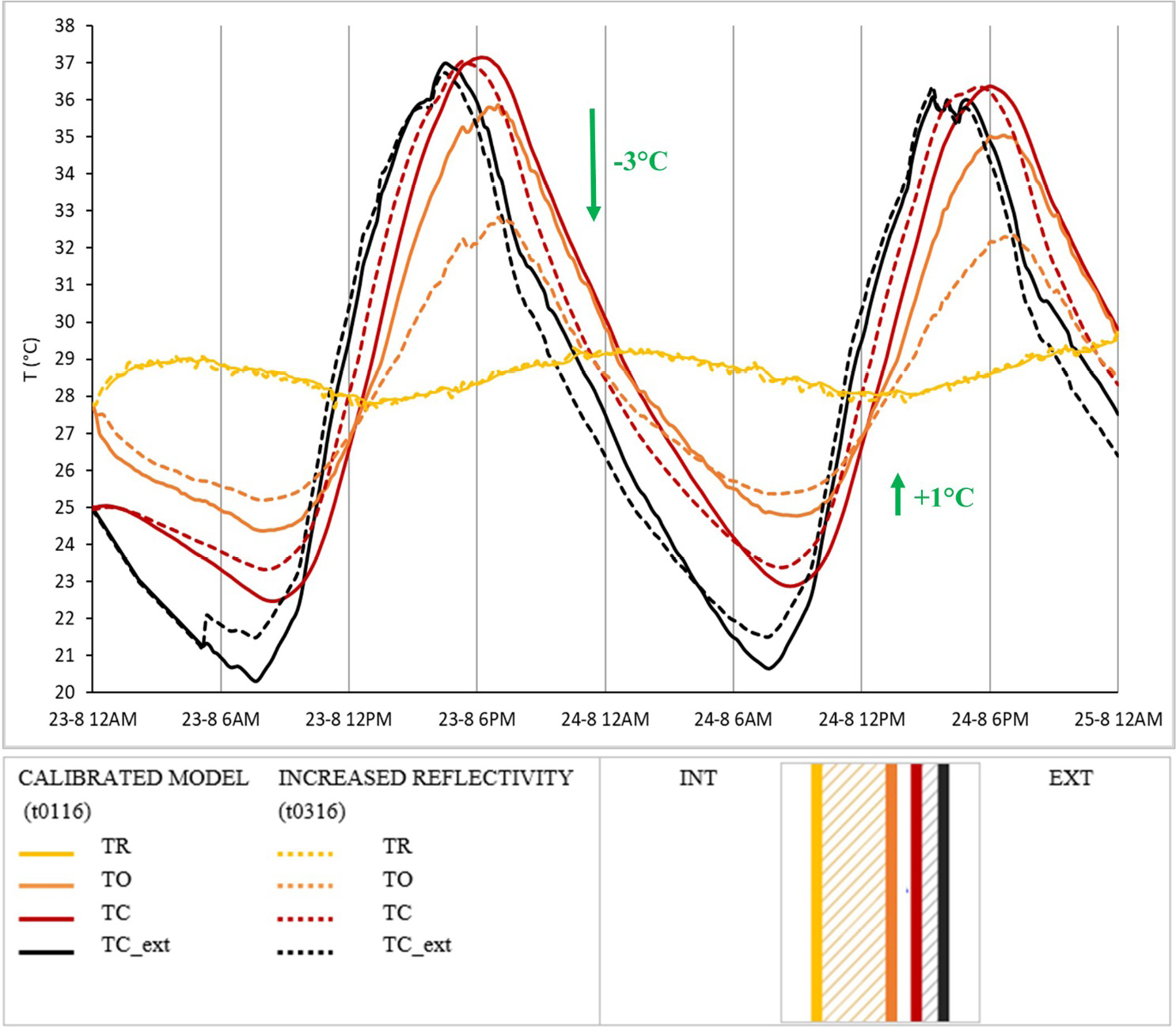
For example, the emissivity of the OSB panel facing the ventilated cavity was changed, and the results were analysed. The objective was to evaluate and quantify the effect of an increased reflectivity of the inner surface of the ventilated cavity – that can be obtained by painting the OSB panel with a reflective paint or by placing a reflective foil on it – on the envelope’s thermal behaviour, considering summer days with a clear sky.
The comparison between the calibrated model (t0116) and the new case with increased reflectivity (t0316) is shown in Figure 8. What can be noticed is that an increase from 0.2 to 0.8 in the reflectivity value can produce a 3°C reduction of TO maximum peaks and a 1°C increase of the lowest peaks. The results show a change in the heat flux entering the building from 10 W/m2 to -10 W/m2 over the day.
4. Conclusions
The research presented focuses on the development of a solver-efficient multi-region 2D CFD model for the thermal analysis and optimisation of ventilated façades with external massive cladding. The CFD model was calibrated and validated against the data collected during the experimental monitoring of the timber-concrete composite ventilated façade of a new building located in the north of Italy (described in [19]). Several CFD models for the thermal analysis of ventilated façades were found in the literature, however they were all tested to study ventilated façades with thin external cladding. In contrast, the current research focused on the development of a CFD model for ventilated façades with external massive cladding.
The model was set by using the open-source software OpenFOAM [20] to make it accessible to everyone. Also, it was developed in two dimensions to be as simple as possible and it was enhanced in terms of computational effort: a mesh refinement study was performed to select the optimal discretization. Finally, a new “frozen-unfrozen flow” solver was implemented to allow faster simulations while still maintaining good accuracy of the results. In case the “frozen–unfrozen flow” solver is used, the simulations are much faster than using the original solver: considering simulations for 24 h real-time, the new solver can increase the speed of the simulation up to 45 times, keeping an acceptable margin of error in the results. This significant acceleration is impressive when considering the relatively simple modification of the algorithm.
The calibrated CFD model obtained can be used to assess the thermal performance of TCC ventilated façades in different configurations (e.g., a different air cavity depth, concrete slab thickness, colour and material of the surfaces, orientation, ventilation type, etc.), allowing the optimization of the building envelope solutions, partially avoiding the expensive and time-consuming construction of mock-ups. Accurate research in this respect might be interesting for system manufacturers, in order to further develop their products to comply with the different project requirements, and for designers, to better choose and specify the systems to be used. Certainly, experiments for validation remain key for benchmarking a CFD model prediction. However, the new opportunities offered by calibrated CFD models for façades more than balance the efforts needed to create them from our perspective.
Additionally, the study represents an important step towards digital twins for TCC ventilated façades, since the calibrated CFD model can make predictions faster than real-time [22]. For example, the model might be used together with advanced control strategies to minimize a building’s energy consumption. A 1:1 digital twin of the façade is required, which might necessitate the digitalization of existing buildings. Future work might address these limitations, e.g., through a refined validation study or a sensitivity analysis with respect to the assumed boundary conditions to mitigate these limitations.
At a broader level, the research aims to contribute to the knowledge regarding the thermal performance of ventilated façades composed of an internal lightweight wall structure and an external massive cladding.
5. Authors Contributions
Conceptualization, P.S.; Methodology, P.S.; Software, P.S.; Validation, P.S.; Formal Analysis, P.S.; Investigation, P.S.; Data Curation, P.S.; Writing – Original Draft Preparation, P.S.; Writing – Review & Editing, P.S. and S.G.; Visualization, P.S. and S.G.; Supervision, M.E.S. and L.A.; Project Administration, M.E.S. and L.A.
6. References
[1] Asdrubali F, Ferracuti B, Lombardi L, Guattari C, Evangelisti L, Grazieschi G (2017) A review of structural, thermo-physical, acoustical, and environmental properties of wooden materials for building applications. Building and Environment 114:307–332. https://doi.org/10.1016/j.buildenv.2016.12.033
[2] Vololonirina O, Coutand M, Perrin B (2014) Characterization of hygrothermal properties of wood-based products – Impact of moisture content and temperature. Construction and Building Materials 63:223–233. https://doi.org/10.1016/j.conbuildmat.2014.04.014
[3] Fortuna S, Mora TD, Peron F, Romagnoni P (2017) Environmental Performances of a Timber-concrete Prefabricated Composite Wall System. Energy Procedia 113:90–97. https://doi.org/10.1016/j.egypro.2017.04.024
[4] Pastori S, Mereu R, Mazzucchelli ES, Passoni S, Dotelli G (2021) Energy Performance Evaluation of a Ventilated Façade System through CFD Modeling and Comparison with International Standards. Energies 14(1):193. https://doi.org/10.3390/en14010193
[5] Destro R, Boscato G, Mazzali U, Russo S, Peron F, Romagnoni P (2015) Structural and Thermal Behaviour of a Timber-concrete Prefabricated Composite Wall System. Energy Procedia 78:2730–2735. https://doi.org/10.1016/j.egypro.2015.11.614
[6] Patania F, Gagliano A, Nocera F, Ferlito A, Galesi A (2010) Thermofluid-dynamic analysis of ventilated facades. Energy and Buildings 42(7):1148–1155. https://doi.org/10.1016/j.enbuild.2010.02.006
[7] Giancola E, Sanjuan C, Blanco E, Heras MR (2012) Experimental Assessment and Modelling of the Performance of an Open Joint Ventilated Façade during Actual Operating Conditions in Mediterranean Climate. Energy Build 54:363–375. https://doi.org/10.1016/j.enbuild.2012.07.035
[8] Ciampi M, Leccese F, Tuoni G (2003) Ventilated Facades Energy Performance in Summer Cooling of Buildings. Sol Energy 75:491–502. https://doi.org/10.1016/j.solener.2003.09.010
[9] Giancola E, Sánchez MN, Friedrich M, Kalyanova Larsen O, Nocente A, Avesani S, Babich F, Goia F (2018) Possibilities and Challenges of Different Experimental Techniques for Airflow Characterisation in the Air Cavities of Façades. Journal of Facade Design and Engineering :34-48 Pages. https://doi.org/10.7480/JFDE.2018.3.2470
[10] Gagliano A, Nocera F, Aneli S (2016) Thermodynamic Analysis of Ventilated Façades under Different Wind Conditions in Summer Period. Energy Build 122:131–139. https://doi.org/10.1016/j.enbuild.2016.04.035
[11] Jensen J, Bartak M, Drkal F (2007) Modeling and Simulation of a Double-Skin Facade System. In: ASHRAE Transactions 2002 - Honolulu, HI, United States, pp 1251-1259
[12] Manz H (2003) Numerical Simulation of Heat Transfer by Natural Convection in Cavities of Facade Elements. Energy Build 35:305–311. https://doi.org/10.1016/S0378-7788(02)00088-9
[13] Xamán J, Álvarez G, Lira L, Estrada C (2005) Numerical Study of Heat Transfer by Laminar and Turbulent Natural Convection in Tall Cavities of Façade Elements. Energy Build 37:787–794. https://doi.org/10.1016/j.enbuild.2004.11.001
[14] Pappas A, Zhai Z (2008) Numerical Investigation on Thermal Performance and Correlations of Double Skin Façade with Buoyancy-Driven Airflow. Energy Build 40:466–475. https://doi.org/10.1016/j.enbuild.2007.04.002
[15] Safer N, Woloszyn M, Roux JJ (2005) Three-dimensional simulation with a CFD tool of the airflow phenomena in single floor double-skin facade equipped with a venetian blind. Solar Energy 79(2):193–203. https://doi.org/10.1016/j.solener.2004.09.016
[16] Sanjuan C, Suárez MJ, González M, Pistono J, Blanco E (2011) Energy performance of an open-joint ventilated façade compared with a conventional sealed cavity façade. Solar Energy 85(9):1851–1863. https://doi.org/10.1016/j.solener.2011.04.028
[17] Baldinelli G (2009) Double Skin Façades for Warm Climate Regions: Analysis of a Solution with an Integrated Movable Shading System. Build Environ 44:1107–1118. https://doi.org/10.1016/j.buildenv.2008.08.005
[18] Stazi F, Ulpiani G, Pergolini M, Magni D, Di Perna C (2018) Experimental Comparison Between Three Types of Opaque Ventilated Facades. TOBCTJ 12(1):296–308. https://doi.org/10.2174/1874836801812010296
[19] Pastori S (2024) Timber-Concrete Composite Ventilated Envelope Systems. Experimental and Numerical Investigations for Thermal Performance Control and Optimization. Dissertation, Politecnico di Milano, Milan
[20] OpenFOAM (2022) OpenFOAM v2206. https://www.openfoam.com/. Accessed 28 Oct 2025
[21] ISO/CEN (2017) EN ISO 6946:2017 Components and Building Elements—Thermal Resistance and Thermal Transmittance—Calculation Methods.
[22] Tahmasebinia F, Lin L, Wu S, Kang Y, Sepasgozar S (2023) Exploring the Benefits and Limitations of Digital Twin Technology in Building Energy. Applied Sciences 13(15):8814. https://doi.org/10.3390/app13158814