Multi-Objective Optimization of Facade Retrofit Solutions for Italian Residential Precast Concrete Buildings
Department of Civil and Environmental Engineering, University of Florence, Italy
Email: neri.banti@unifi.it; cecilia.ciacci@unifi.it; vincenzo.dinaso@unifi.it; frida.bazzocchi@unifi.it
*Corresponding author
Abstract. The current European policies aim to obtain a significant reduction in CO2 emissions, targeting a carbon-free economy by 2050, and propose an extensive renovation plan for the residential building heritage. The majority of Italian residential buildings predates energy-saving regulations and are currently affected by several environmental issues. This paper proposes retrofitting measures for the external walls of an existing residential precast building dating back to the 1980s, located in the Province of Florence. Two different technological solutions have been evaluated for the redevelopment of facades, featuring recladding with a Vêture system and a rainscreen solution. The methodology of the research implements a BIM-based approach: the building was modelled in the Revit environment, while optimized facade layouts were generated using an algorithm developed in Grasshopper, considering various design parameters. As for the Vêture solution, the chosen configuration reduces the total number of panels installed, minimizing at the same time the use of special components. A similar approach has been adopted in the case of the rainscreen solution, but resorting to an optimization procedure through genetic algorithms. The solutions of interest have been hence selected in the Pareto front, considering the type and number of panels. The retrofit interventions explored improved the building’s energy label from F to E, also enhancing its aesthetic quality.
Keywords: Residential building stock, precast structure, energy retrofit, optimization, BIM.
1. Introduction
The challenging environmental strategy set by the European Union to achieve a carbon-free economy makes redevelopment interventions addressing the existing building heritage extremely urgent. In Italy, the existing residential building stock accounts for about 12.5 million facilities, 60% of which was built before 1970 when national standards for energy saving were still lacking [1]. As a consequence, 71% of the Italian residential building stock currently belongs to low standards considering the energy labelling classification (E, F and G), being characterised by an average energy performance index equal to 185.4 kWh/m2y. As previously introduced, the age of public residential structures is a detrimental factor that heavily affects the energy performance, as well as the architectural and aesthetic quality, of social housing buildings.
Between the 1960s and 1980s, precast systems were adopted in Tuscany to meet the increasing demand for housing facilities, particularly in Florence, Sesto Fiorentino and Prato. The recourse to prefabricated, standardized solutions, replicable in different contexts, was highly promising at that time to reduce costs and to speed up construction processes, but resulted in several issues over time. Nowadays, these buildings are characterised by inadequate structural behaviour, rigid structural and architectural schemes, and a lack of aesthetic refinements. Moreover, the technological solutions adopted, combined with the low quality of the materials used, have determined poor thermal insulation, inadequate internal comfort conditions and high annual energy demand. In this context, retrofitting interventions are necessary but can sometimes be complex and challenging due to structural and technological limits, as reported by some authors in the literature. Ciulla et al. [2] remark on the difficulty of selecting the proper redevelopment solutions for facades, while Ballarini et al. [3], following a cost-optimal evaluation, recommended acting on heat generators as the most cost-effective intervention for the same building stock, also analysed by Corrado et al. [4]. Other studies deal with specific retrofit solutions, both at the building scale [5] and urban level [6-7].
The widespread diffusion of new digital and computational tools has been reshaping scientific research trends over the last decades. Several researchers propose BIM-based methodologies applied to the existing building heritage [8-9] for its energy and structural retrofit [10] and its management over the life cycle [11-12]. The advantages of BIM-based approaches also rely on interoperability with tools for structural, energy, and environmental simulations or Life Cycle Assessment analysis [13]. Recently, some authors have proposed the integration of emerging artificial intelligence (AI) into BIM modelling and parametric design using the Visual Programming Language (VPL) tool [14-16]. The research on the energy retrofit of existing building facades using innovative design tools mainly deals with dynamic solar shading systems and adaptive facades, without considering traditional solutions well-established in the market.
This paper aims to demonstrate the potential of using VPL (Visual Programming Language) tools in parametric design procedures to highlight how optimization techniques can support decision-making, particularly in the assessment phase of technological and economic feasibility.
The research focuses on the design of potential retrofit interventions for an existing precast multi-storey residential building chosen as a case study. Acting on the facades was prioritized given the greater dispersing surface, the currently low thermal resistance and the poor aesthetic quality. In this regard, Vêture and rainscreen facades were foreseen in the research to include two distinct technological solutions that are commercially available and commonly used in current practice. The study was carried out implementing digital tools within a BIM-based approach. At first, the building was modelled in the BIM environment through Revit software starting from the original architectural and structural project documents. The modelling phase was useful to organize, systemize and manage all the retrieved building data as well as to provide a reference digital twin for the subsequent analyses. A Grasshopper script was developed to explore different layouts for facade recladding panels and to optimize their arrangement through two different approaches.
2. Methodology
The research was developed by applying the methodological steps detailed below and illustrated in Figure 1:
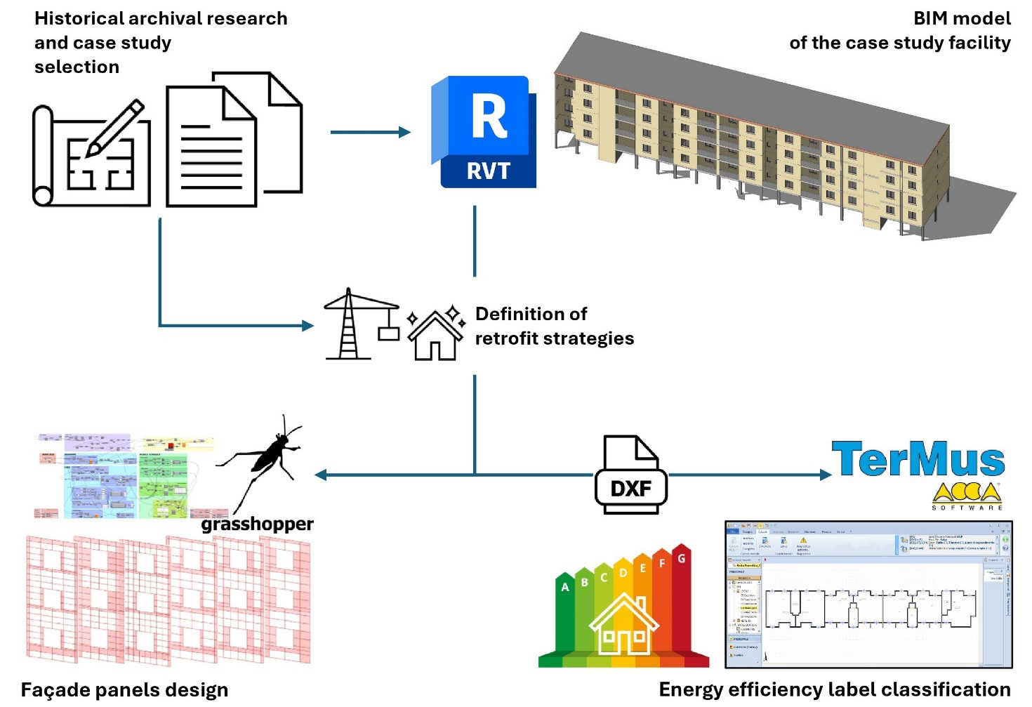
– Historical archival research. This phase is based on previous research conducted by the authors that resulted in the classification of the different precast concrete systems used within the 1970s and 1980s to build social and public housing in the Florentine area. An exhaustive document acquisition campaign from Casa Spa Archive was held at the time, investigating original design projects, the correspondence during the construction phase, patents, bills of quantities and cost inventories. The original documents were scanned to obtain digitalized materials, and in the meantime, a photographic on-field survey was conducted to assess discrepancies with real conditions.
– Case study building selection. Following a careful examination of the available material, a 5-storey linear building sited in the Municipality of Sesto Fiorentino, and built between 1981 and 1985 using the CA-AB system, was chosen as the reference case. This choice was based on the documentary coverage of the building, the widespread adoption of the same construction system during that period, and on its peculiarities, which make the results of this study extendable to other kinds of building types.
– BIM-modelling phase. The case study was modelled in a BIM environment using Revit software, following the architectural, structural, and technological details retrieved in the specifications of the original design documents and considering the photographic documentation acquired. The incongruences assessed between the various design documents available were also solved to produce a reliable as-it-is condition model.
– Definition of retrofit strategies. Two different technological solutions among those available on the market were considered for the architectural and energy redevelopment of existing facades. Both configurations were designed to achieve the same thermal resistance and convey equivalent energy savings for heating demand. The first one is a Vêture recladding system, composed of a horizontal metal substructure and a panel (6.6 cm thick, U=0.54 W/m2K) made of fibre-reinforced composite mortar finishing and a thermal insulation layer (EPS additivated with graphite) with open joints. The second alternative is a traditional rainscreen cladding system with a metal substructure, a thermal insulation layer (wood fiber - 6 cm thick, λ = 0.038 W/m2K), and completed with low-thickness (3.5-20.5 mm) ceramic tiles as external finishing.
– Facade panels design in the Grasshopper environment. The building’s geometry was directly imported from Revit into the Rhinoceros environment, via Grasshopper plug-ins, referring to a portion of the external facade. A series of VPL scripts was developed to define the geometry of the facade recladding panels for both the retrofit solutions, including optimization and design optioneering algorithms.
– Energy efficiency label classification. To quantify the effectiveness of the energy retrofit proposed, the building geometry was imported in TerMus software to evaluate both pre and post redevelopment state following the current Italian energy standards [17-18]. A gas condensing boiler (efficiency equal to 0.7) was selected as heat source and the setpoint temperature during winter was set equal to 20°C to reflect the residential intended use. Natural ventilation for minimum air change rate and the domestic hot water demand have been included in the energy balance. However, some simplified assumptions were made: apartments were modelled as homogeneous zones given the uniform operation conditions, and lighting loads were not accounted for, as well as the internal heat gains.
2.1 The Case Study
The case study (Figure 2) is a 5-storey linear building located in the municipality of Sesto Fiorentino (Florence). This building was commissioned by the IACP (Istituto Autonomo Case Popolari) of the Province of Florence in 1981 and completed on 1st July 1985.
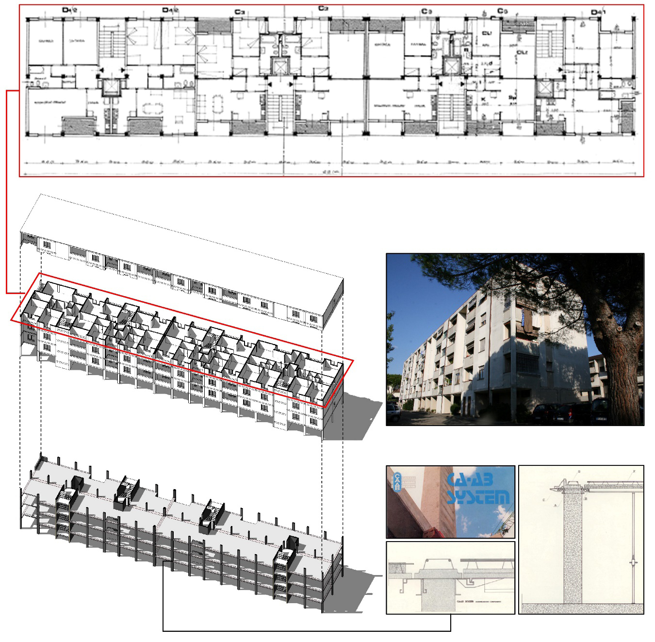
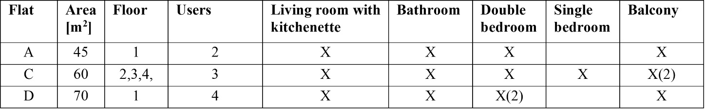
The building, oriented along the NE-SW direction, has a rectangular shape with main dimensions equal to 63.10 × 11 m and a gross floor area of about 700 m2. It is composed of two different structural units with seismic joints at 27.50 m along the prevailing axis. The ground floor (2.40 m high) hosts private cellars, technical rooms and collective open spaces with pilotis, while the other four upper levels (2.70 m high) comprise a total of 30 apartments of different sizes (Table 1). Vertical connections are ensured by four lifts and stair blocks.
Considering the elevation, the openings are aligned and present the same dimensions. In the main fronts: 1.40 × 1.40 m for windows and 0.90 × 2.40 m for balcony glazing doors. On secondary fronts, only smaller openings (0.80 × 0.90 m) can be found.
As far as the structure is concerned, it was built adopting the CA-AB system [19]. This patent foresees a precast reinforced concrete frame structure with single-story columns and beams in slab thickness (24 cm), with structural joints made by additional concrete casting. The beams have a trapezoidal cross-section with extrados longitudinal reinforcement bars. The floor slabs are partially prefabricated and lightened with polystyrene blocks. The external walls feature the following stratigraphy (total thickness 19.5 cm) from the internal to the external side: plasterboard panel (1 cm thick), polystyrene thermal insulation (5 cm), hollow bricks (12 cm) and external plaster (1.5 cm). These facades are characterised by the following thermal properties: thermal transmittance U=0.544 W/m2K, surface mass Ms=96 W/m2K, and periodic thermal transmittance YIE=0.4 W/m2K. The roof slab is completed with a polystyrene thermal insulation (5 cm thick) and a bituminous waterproof sheet as a finishing layer (1.5 cm). For the calculation of the thermal properties, UNI 10351 was considered [20]. As for the internal walls, they were realized recurring to dry-wall partitions.
2.2 Facade panels design
Figure 3 provides a general overview of the VPL Grasshopper script, briefly described in this paragraph to highlight its crucial components and the decision-making approaches followed for selecting the most suitable design alternative.
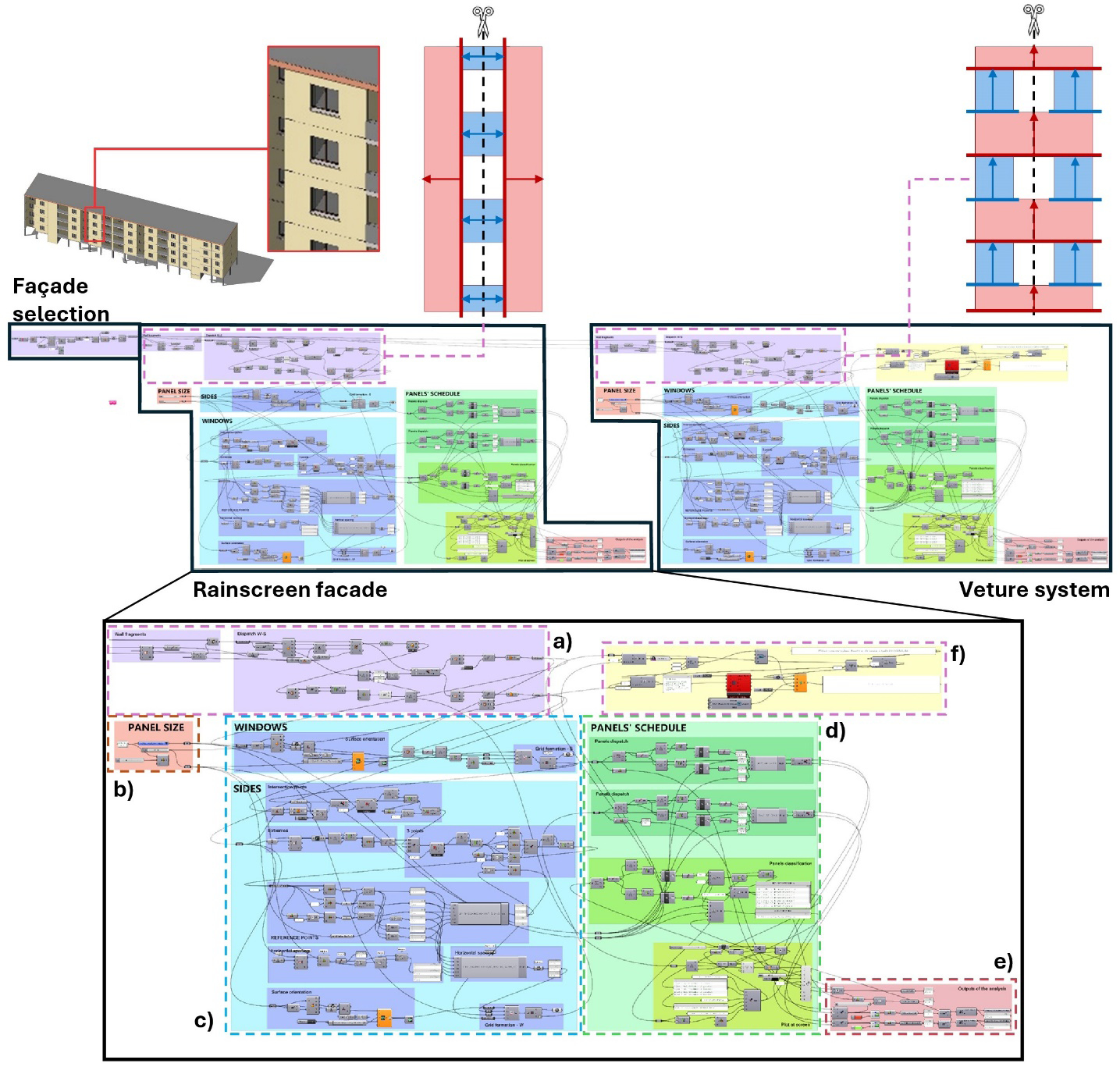
The script can be divided into three different macro-sections: a block of instructions is initially meant to select and import the portion of the facade under consideration directly from the BIM model, while the two others are dedicated to the definition of the panels’ layout and selection of the most suitable configuration for both the Vêture and rainscreen alternatives. The latter sections are made up by using the same logic and procedural steps. Going into detail and referring to the numbering proposed in Figure 3:
a) Segmentation of the facade: this operation is meant to subdivide the geometry of the current facade state into homogeneous portions. This preliminary operation is crucial to defining the arrangement of the facade cladding panels in the subsequent steps.
b) Definition of panels’ size: through a numeric slider, the width and height of each panel can be set, with different values allowed according to the technological solution chosen:
– Vêture system: dimensions derived from commercially available products. The standard height of the panel can be either 0.45 m or 0.60 m, while the width associated with each varies from 0.45 to 0.90 m in the first case and from 0.60 to 1.20 m in the latter.
– Rainscreen facade: as previously introduced, the solution featuring low-thickness ceramic cladding tiles allows for a wider range of geometries; in this case, both width and height were assumed to vary between 0.10 m and 1.10 m with increments of 0.10 m.
c) Definition of panels’ layout: following the previously introduced facade segmentation and adopting the dimensions set in the b) section, the layout of panels was generated. The following assumptions have been introduced when defining the constraints for tiles’ arrangement:
– Vêture system: given the peculiarities of this technology, horizontal bands between windows were addressed as the reference sections. In these areas, rows of cladding panels were assumed to begin from the bottom side and to be arranged symmetrically with respect to the whole facade. Sections adjacent to the windows were subsequently clad following the same logic.
– Rainscreen facade: to exploit the variability of panels’ shape and size ensured by this solution, the vertical sections located at the sides of the windows were primarily addressed in this case. In the smaller vertical sections between windows, the cladding panels were consequently aligned with the ones in the main sections. To respect the vertical symmetry of the facade, the width of the panels in these portions was obtained through an approximation based on this formula: W2=L/[round(L/W1)], where W1 represents the width of panels in the main sections and W2 the one to be determined, and L stands for the total length of the same section.
The portions of the facade chosen as mainly influencing in both configurations are highlighted in red in Figure 3. The layout in the blue sections is hence derived from the arrangement of tiles in the former. In the same schemes, the thick colored lines point out the starting alignment for the creation of the panelling grid and the arrows express its direction of development.
d) Creation of the panels’ schedule: the main relevant information about each alternative layout is collected and plotted on the screen. A different color was associated to each panel type generated, providing immediate visual feedback. The report includes the following parameters:
– Number of standard panels, accounting for all the tiles whose dimensions are exactly the ones set in advance;
– Number of non-standard panels, accounting for all the tiles differing from the standard ones to fit the remaining portions of the facades. For each type of panel, the width, height, and number of elements are provided;
– Dimension of the shortest element serves as a parameter to evaluate the feasibility of the solution and consequently to avoid configurations with excessively small components.
e) Output of the analysis: the main outcomes of the analysis are collected to be later used as evaluation criteria:
– Vêture system: the total number of panels and the area covered by non-standard panels;
– Rainscreen facade: the total number of panels, the number of panels’ typologies, and the number of non-standard tiles.
f) Evaluation of feasible alternative configurations: both design optioneering and optimization procedures were set to select the preferred layout among those generated, acting on the variables related to the size and geometry of the cladding panels. In particular, the former was applied in the case of the Vêture solution because of the limited number of configurations to be evaluated. The TT Colibri and DesignExplorer components [21-22] have been included in the algorithm for this purpose. On the other hand, a multi-objective optimization was conducted for the rainscreen recladding through the Octopus component, featuring a genetic algorithm. The height and width of the panels represent the variable parameters to act on, while the optimization was set to minimize the total number of panels used and the number of non-standard ones. The total number of panels and the area covered by non-standard panels were specified as evaluators in the design optioneering analysis. However, in this case, the selection of the most suitable solution is carried out directly by the designer, rather than relying on the autonomous computational capability of the chosen genetic algorithm. The selection of these evaluation parameters stems from considerations on design for manufacturing and assembly: as recognized in the literature, minimizing non-standard panels can enhance economic feasibility by reducing fabrication and manufacturing costs, can support environmental sustainability by preventing material waste, and can speed up the construction process acting on the on-site labor complexity [23-24].
3. Results and discussion
For a better comprehension of the results, this section has been divided into different sub-paragraphs addressing the various topics covered in the study. At first, results about facade layout design will be presented, in distinct sections for the Vêture and rainscreen configuration, while the energy label classification will be introduced later.
3.1 Vêture system
In the case of the Vêture recladding, the combination of possible height and width values available on the market led to six different solutions. Figure 4 presents them, numbered A-F, according to the visualization scheme proposed by DesignExplorer. The interactive interface of this tool allowed for the filtering and selection of the configurations by imposing restrictions on the input variables or outcomes of interest in each vertical column. As previously introduced, reducing non-standard panels was assumed to be particularly relevant for the final selection, along with limiting the total number of panels, which was meant to simplify installation procedures. In the graphical representations of the different layouts included in Figure 4, the non-standard tiles are highlighted in red.
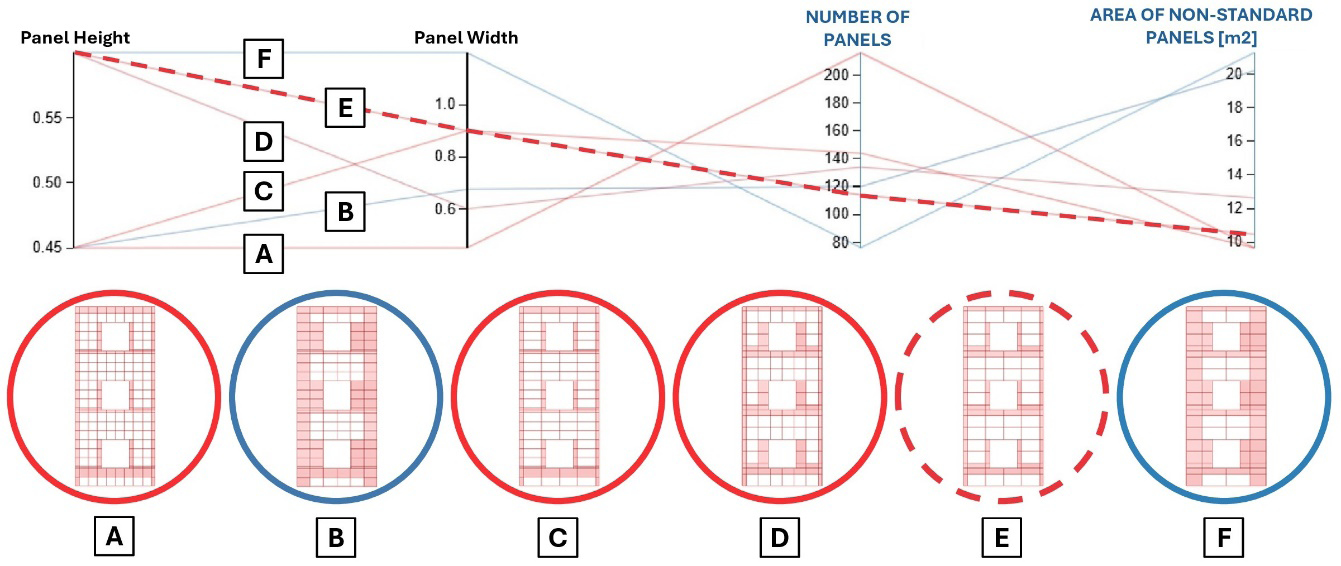
The different configurations obtained will be synthetically described in the following, along with some general considerations about the results obtained in this case:
– Solution A (0.45 × 0.45 m): it foresees 216 panels, the highest value among the possible alternatives produced given the smallest size of the tiles, but significantly reduces the number of non-standard elements (9.66 m2);
– Solution B (0.45 × 0.675 m): it reduces the number of panels to 120, but it is affected by a considerable area covered by non-standard units (20.19 m2), making it the least efficient option;
– Solution C (0.45 × 0.9 m): it requires 144 panels but maintains the same non-standard area as Solution A, offering improved efficiency;
– Solution D (0.6 × 0.6 m): it involves 134 panels, even if with a slightly higher amount of non-standard units (12.63 m2); for this reason, despite being less efficient than other options, it may work as an acceptable compromise solution;
– Solution E (0.6 × 0.9 m): reduces the total number to 114 modules and lowers the non-standard area to 10.47 m2 units, offering an optimal balance between modularity and waste reduction;
– Solution F (0.6 × 1.2 m): with only 76 panels, it features the lowest amount of panels used given the large dimensions of the cladding elements. However, this affects the number of non-standard pieces, which is sensibly higher than that of other solutions (21.27 m2).
Configurations B and F, highlighted in blue in Figure 4, proved to be severely penalized by a higher number of non-standard components, as both show an area covered by irregular tiles approximately double with respect to the other solutions. However, it must be remarked that layout F is characterised by the absolute lowest number of elements, allowing for a significant speedup in installation processes by using large-format panels, which could be a crucial factor in some cases. All the other configurations present similar performance in terms of non-standard panels, but present a total number of panels ranging in a wide interval, ranging from 216 in solution A to 114 in solution E. The latter, outlined with a dashed red line in Figure 4, was identified as the most promising solution: it minimizes the use of special components while also reducing the total number of panels, thanks to the implementation of large tiles (0.6 × 0.9 m).
3.2 Rainscreen system
The optimization of the panels’ arrangement for the rainscreen facade recladding was performed using the Octopus plug-in in the Grasshopper environment. A total of 60 generations, each with a maximum of 75 individuals, were autonomously produced during the optimization process, and the results are illustrated in Figure 5. The different alternatives are represented as boxes and plotted in a 3D space (XYZ), where each axis expresses one of the evaluation parameters: types of panels, total number of panels, and number of non-standard panels. The configurations highlighted in red belong to the so-called “Pareto front”, which includes all of the “non-dominated” solutions. This means that no single solution in this set can be improved in one objective without causing a degradation in at least one other. Within the context of facade retrofitting, this implies that each layout on the Pareto front reflects a specific compromise among the relevant competing performance indicators. For the optimization carried out in this research, three distinct solutions emerged as the most promising under the given boundary conditions. All the layouts considered features panels 0.90 m high but differ in terms of width:
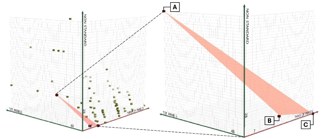
– Solution A: despite having the lowest number of panel types, it requires the highest number of cladding tiles due to their limited width (0.10 m);
– Solution B: this represents a balanced compromise between the extremes, involving a limited number of both total panels and non-standard ones;
– Solution C: large-size panels enable to reduce their number, even if nine different formats are needed. Moreover, it must be remarked that enlarging the panel size may result in undesired complexity of the substructure.
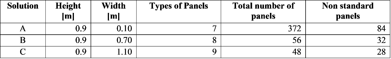
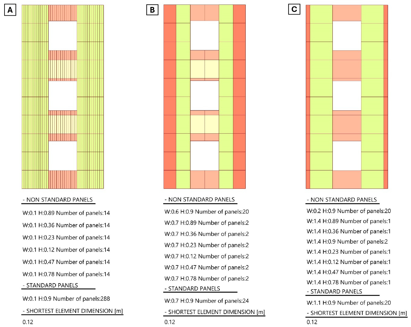
Table 2 summarizes the key properties of each solution, while Figure 6 illustrates their final visual appearance along with the panel schedule generated by the Grasshopper script.
To support informed decision-making, a structured interpretative framework can be adopted. Project stakeholders should first establish the relative importance of the objectives based on project-specific constraints. Prioritizing selection criteria can lead to the exclusion of undesired solutions from the very beginning of the decision-making process. For instance, if minimizing labour time is considered mandatory, solutions with fewer total panels may be addressed. Later, for a comparative trade-off analysis, each solution on the Pareto front should be evaluated, looking for the one that balances both quantitative and qualitative factors. Finally, external factors not initially considered, such as the market availability of non-standard components, initial investment cost, and architectural or aesthetic preferences, should be incorporated. These considerations often lead to preferring one solution over others, even when purely technical trade-offs are balanced.
Remarkably, in the study presented, all non-dominated solutions belonging to the Pareto front are eligible layouts for retrofitting, considering the rainscreen facade technological solution. The final selection among these alternatives should be informed by the project’s priorities – whether cost minimization, architectural uniformity, or ease of execution is paramount. Additionally, the availability of suppliers for non-standard components and the client’s aesthetic preferences play a decisive role.
In the Vêture system, layouts are imposed through precise values of design parameters (such as panels’ width). In contrast, the rainscreen system offers a higher level of freedom in design selection, ensured by specific cladding materials, which may lead to a preference for other configurations over the optimized ones. Moreover, the recourse to rainscreen solution can allow to satisfy higher quality standards in terms of materials used, aesthetic finishing and cladding panels layout, and effects on more aspects of building performance (e.g. moisture removal, micro-ventilation in air gaps). In both facade technologies, it has to be remarked that the use of large-size panels should be carefully evaluated also in relation to constructability limitations associated with site accessibility, scaffolding size, or the need for dedicated installation equipment (e.g. platforms, lifting cranes).
3.3 Energy label
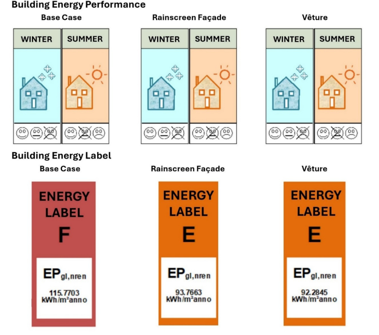
The energy efficiency classification of the existing building highlights several issues related to the external envelope’s performance, particularly during the winter season, as shown in Figure 7. The thermal transmittance of both the external walls and the roof slab do not meet the minimum required thermal transmittance for climate zone D. This results in a Global Average heat transfer coefficient for transmission (H’T) equal to 0.756 W/m2 and the heat losses through the external envelope (Qh,TR) equal to 71% of the total losses. As regards the calculation of the design peak load, the energy losses for transmission were calculated to be 67 kW, while the primary energy demand for heating is over 500 kWh. The presence of about 270 m2 of glazing dispersing surface, characterised by window frames without thermal breaks and single glazing panes, is an additional detrimental factor for the building’s performance during the winter season. In conclusion, the global non-renewable energy performance index (EPgl,nren) is equal to 115.77 kWh/m²/y (energy label F), indicating a low performance of the external envelope for the winter season. This evidence justifies the urgency of intervening on the external wall stratigraphy of these types of buildings to improve their energy performance, indoor thermal conditions for the occupants, and their visual and aesthetic appeal. Both redevelopment measures foreseen for the external walls result in an improvement of energy performance with a consequent upgrade in the energy label. At first, an enhancement of the thermal properties of the external walls can be achieved: the solution with the rainscreen system is characterised by a thermal transmittance equal to 0.29 W/m2K while the Vêture cladding system reaches a value of 0.27 W/m2K. On the other hand, the surface mass is affected to a lesser extent compared to the base case (133 kg/m2), given the lightweight nature of the recladding applied. For both redevelopment measures considered, a decrease in energy losses through the external envelope equal to 5% and a reduction in the primary energy demand of about 90 kWh occur. In conclusion, for the Vêture solution, an energy label E is obtained with EPgl,nren = 93.77 kWh/m2y; the same energy label E is ensured by the rainscreen recladding, even if with a slightly lower EPgl,nren (92.28 kWh/m2y).
4. Conclusions
The research discussed in the paper demonstrates the integration of digital tools, such as Grasshopper and Octopus, to systematically explore facade recladding configurations that balance energy efficiency, material optimization, and aesthetic considerations.
Within the study workflow, the BIM modeling phase played a crucial role, allowing for the digital reconstruction of the case study building based on the currently available design documents, ensuring the development of a reliable as-is model, essential for subsequent analyses and optimization. However, some inconsistencies were identified in the original documentation, indicating the potential need for further on-site verification to enhance data accuracy and address any unresolved discrepancies.
A key contribution of this work is the application of multi-objective optimization in defining panel layouts for two facade retrofit solutions. By employing parametric modeling and genetic algorithms, the methodology minimizes the use of non-standard components, optimizes panels distribution, and reduces installation complexity. The computational analysis enabled the identification of Pareto-optimal solutions, providing a set of trade-offs between conflicting design criteria.
The energy models produced highlighted the effectiveness of energy retrofitting of existing residential building stock: improving building thermal performance results in a reduction of energy losses and an upgrade from energy label F to E. Large-scale applications of these interventions can substantially benefit from the application of data-driven digital workflows to speed up and optimize design procedures by informed decision making on a wide set of facilities.
At this stage, the study is currently affected by some limitations. Structural verification and substructure system design are essential to ensure safety and compliance, but the analysis carried out at this stage of the research was simply preliminary and meant to ensure the feasibility of the interventions proposed. These aspects must be hence taken into account at later stages of design with a detailed assessment. Moreover, the energy performance of the facility, currently assessed by performing simple energy labelling, should be refined through detailed energy modelling simulations.
Future research should expand upon these findings by including additional evaluation criteria, such as energy efficiency, LCA evaluations, or load-bearing implications (to account for the effects on yearly demand, environmental impact, and to consider limitations related to different construction typologies and load-bearing capacity). Integrating artificial intelligence-driven generative design could be another enhancing factor to both speed up decision-making and ameliorate the overall quality of the alternatives investigated.
5. References
[1] ENEA (2024) La consistenza del parco immobiliare nazionale. ENEA, Rome. https://www.pubblicazioni.enea.it/le-pubblicazioni-enea/edizioni-enea/anno-2024/la-consistenza-del-parco-immobiliare-nazionale.html
[2] Ciulla G, Galatioto A, Ricciu R (2016) Energy and economic analysis and feasibility of retrofit actions in Italian residential historical buildings. Energy Build 128:649–659. https://doi.org/10.1016/j.enbuild.2016.07.044
[3] Ballarini I, Corrado V, Madonna F, Paduos S, Ravasio F (2017) Energy refurbishment of the Italian residential building stock: energy and cost analysis through the application of the building typology. Energy Policy 105:148–160. https://doi.org/10.1016/j.enpol.2017.02.026
[4] Corrado V, Ballarini I (2016) Refurbishment trends of the residential building stock: Analysis of a regional pilot case in Italy. Energy Build 132:91–106. https://doi.org/10.1016/j.enbuild.2016.06.022
[5] Pittau F, Malighetti LE, Iannaccone G, Masera G (2017) Prefabrication as Large-scale Efficient Strategy for the Energy Retrofit of the Housing Stock: An Italian Case Study. Procedia Eng 180:1160–1169. https://doi.org/10.1016/j.proeng.2017.04.276
[6] Costanzo V, Nocera F, Detommaso M, Evola G (2024) Decarbonizing cities through electrification: A strategic study for densely built residential districts in Southern Italy. Sustain Cities Soc 113:105651. https://doi.org/10.1016/j.scs.2024.105651
[7] Di Turi S, Stefanizzi P (2015) Energy analysis and refurbishment proposals for public housing in the city of Bari, Italy. Energy Policy 79:58–71. https://doi.org/10.1016/j.enpol.2015.01.016
[8] Lucchi E, Agliata R (2023) HBIM-based workflow for the integration of advanced photovoltaic systems in historical buildings. J Cult Herit 64:301–314. https://doi.org/10.1016/j.culher.2023.10.015
[9] Gigliarelli E, Calcerano F, Cessari L (2017) Heritage Numerical Simulation and Decision Support Systems: an Integrated Approach for Historical Buildings Retrofit. Energy Procedia 133:135–144. https://doi.org/10.1016/j.egypro.2017.09.379
[10] Caterino N, Nuzzo I, Ianniello A, Varchetta G, Cosenza E (2021) A BIM-based decision-making framework for optimal seismic retrofit of existing buildings. Engineering Structures 242:112544. https://doi.org/10.1016/j.engstruct.2021.112544
[11] Sanhudo L, Ramos NMM, Poças Martins J, Almeida RMSF, Barreira E, Simões ML, Cardoso V (2018) Building information modeling for energy retrofitting – A review. Renewable and Sustainable Energy Reviews 89:249–260. https://doi.org/10.1016/j.rser.2018.03.064
[12] Angelo LD, Hajdukiewicz M, Seri F, Keane MM (2022) A novel BIM-based process workflow for building retrofit. J Build Eng 50:104163. https://doi.org/10.1016/j.jobe.2022.104163
[13] Motalebi M, Rashidi A, Mahdi M (2022) Optimization and BIM-based lifecycle assessment integration for energy efficiency retrofit of buildings. J Build Eng 49:104022. https://doi.org/10.1016/j.jobe.2022.104022
[14] McNeel & Associates (2025) Grasshopper for Revit. https://www.rhino3d.com/it/features/rhino-inside-revit/
[15] Ahmad A, Bande L, Ahmed W, Young K, Jha M (2024) AI application in architecture in UAE: Application of an advanced optimized shading structure as a retrofit strategy of a midrise residential building façade in downtown Abu Dhabi. Energy and Buildings 325:114995. https://doi.org/10.1016/j.enbuild.2024.114995
[16] Dastoum M, Sanchez Guevara C, Arranz B (2024) Efficient daylighting and thermal performance through tessellation of geometric patterns in building facade: A systematic review. Energy Sustain Dev 83:101563. https://doi.org/10.1016/j.esd.2024.101563
[17] Ente Italiano di Normazione (2014) UNI/TS 11300-1 Prestazioni energetiche degli edifici. Parte 1: Determinazione del fabbisogno di energia termica dell’edificio per la climatizzazione estiva ed invernale. UNI, Italy
[18] Governo Italiano (2015) Decreto Ministeriale 26 Giugno 2015. Applicazione delle Metodologie di calcolo delle prestazioni energetiche e definizione delle prescrizioni e dei requisiti minimi degli edifici. Gazzetta Ufficiale, Italia
[19] Chiarugi A, Salmesi S, Sani T (1984) Strutture Ca-AB system per edificio multipiano. La prefabbricazione, pp 11–12
[20] Ente Italiano di Normazione (2015) UNI 10351. Materiali e prodotti per l’edilizia. Proprietà termoigrometriche. Procedura per la scelta dei valori di progetto. UNI, Italy
[21] Thornton Tomasetti (2025) Colibri Plugin for Grasshopper. http://core.thorntontomasetti.com/colibri-release/
[22] Thornton Tomasetti (2025) DesignExplorer. https://www.thorntontomasetti.com/capability/design-explorer
[23] Park HK, Ock JH (2015) Developing the preliminary cost estimate for the free-form building facade in conjunction with the panel optimization process. KSCE J Civ Eng 19:1214–1223. https://doi.org/10.1007/s12205-015-0671-y
[24] Pasetti Monizza G, Di Blasio I, Matt DT (2024) Exploring applications of Computational Design techniques and design for manufacturability for costs reduction of prefabricated timber-based facades: The ‘LegnAttivo’ design prototype. Dev Built Environ 19:100489. https://doi.org/10.1016/j.dibe.2024.100489